Converting the Revell/Matchbox 1/72 Flower into an RCN Corvette:
Pt 3
Backdating to a Short Fo'c'sle
|
|
The moment of truth is at hand .. converting the Revell/Matchbox kit
from a late war, long fo'c'sle, hull, into an early war, short fo'c'sle,
corvette. The basic conversion is relatively easy and just requires the
desire to do it.
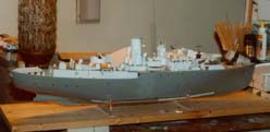
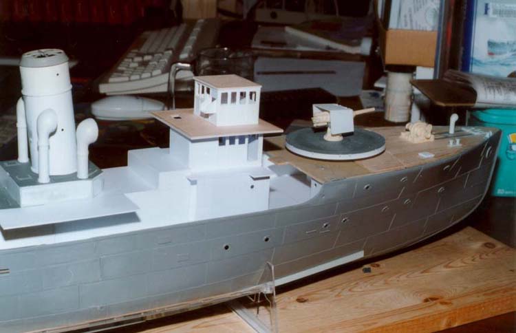
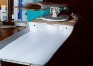
Hull prior to conversion |
I started by cutting the main deck at the new break. This was just behind
the rear of the gun platform, and happily fell at the two locators for
the dodger. I drew a line across the deck and then cut it out using a
new Exacto blade and a steel straight edge. I left a small piece in the
middle for later mounting of the mast.
With the deck cut I placed it on the hull and marked where the hull
should be cut. A template was made by tracing the outline of the kit fo'c'sle
break unto thick card. This was cut out and then used to draw a new outline
at the desired location. On my model this fell on one of the starboard
portholes. Don't worry about that as you can fill it in. Once the break
was drawn I extended the line along the hull to the aft section following
the line of the plating leaving a 3mm deep section that resembles the
kit cap strip along the top of the plating.
 To
cut out the hull section I took a deep breath and used one of the rotary
cutting tools in my Dremel (not the Mini-Mite). I ran this at pretty well
the top speed and cut most of the material away, leaving a couple of millimeters
for cleanup. I then used the thicker of my two rotary saws and cut the
line as close as I dared. The final step was to use a rotary sanding drum
and smooth out the line and the fo'c'sle break. I left the overlapping
section of the hull relatively intact since it will be covered by the
boat deck when done. But I did thin the top of it so it isn't readily
apparent that it is thicker than the surrounding sections. All in all
this was an hour of work from start to finish. To
cut out the hull section I took a deep breath and used one of the rotary
cutting tools in my Dremel (not the Mini-Mite). I ran this at pretty well
the top speed and cut most of the material away, leaving a couple of millimeters
for cleanup. I then used the thicker of my two rotary saws and cut the
line as close as I dared. The final step was to use a rotary sanding drum
and smooth out the line and the fo'c'sle break. I left the overlapping
section of the hull relatively intact since it will be covered by the
boat deck when done. But I did thin the top of it so it isn't readily
apparent that it is thicker than the surrounding sections. All in all
this was an hour of work from start to finish.
Next up was a new deck for the hull. The first step is to determine
where the new deck will sit inside the hull. The aft deck is 16mm below
the level of the gunwale, so I marked off this distance down the hull
and then glued athwartship braces 2mm below these marks. Finally, other
pieces of .040 stock were glued to the sides to support the new deck.
I had intended to use the rest of the kit deck to construct the new deck,
but that would mean an extension would be required where it goes under
the fo'c'sle. Therefore I used .060 Evergreen sheet to do this in one
piece. The deck was traced unto a piece of card and this was cut out.
I then repeatedly cut away sections until it fit in place.
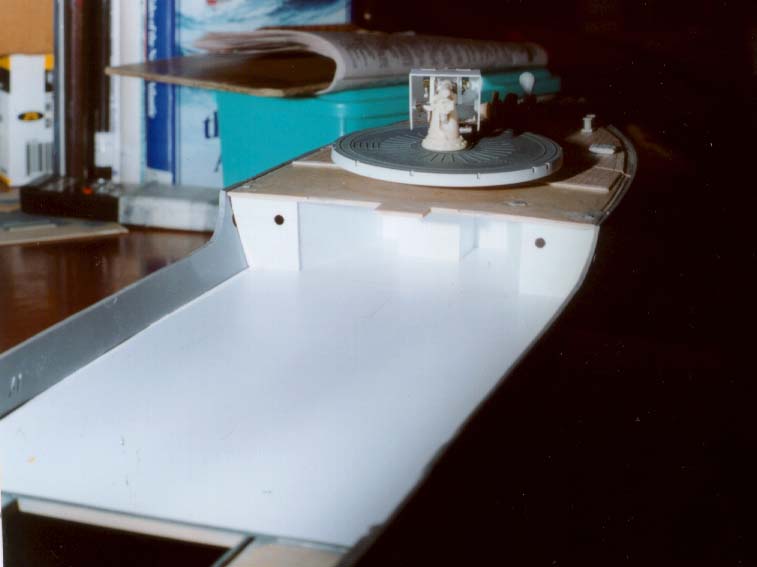
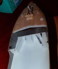
 The
area under the fo'c'sle was what I had been waiting to build ever since
I decided to do a short fo'c'sle Flower. I had always thought that this
was a straight section from side to side. Not so, in fact it is more like
a 'W' in that it angles inwards on each side and has a small hut at the
extreme end of it in the middle. I began this by marking off the centre
of the gun platform on the top of the hull. This line was then extended
down unto the deck to provide the forward end of the enclosed space. The
bow has a pronounced camber to it, therefore I would have to make the
top of the bulkhead slightly curved. To do this I placed the edge of the
remaining deck section on a piece of .040 card and traced the curve. This
was then cut out and placed on the deck and the bow section was test fitted
over top of it. To enable the bulkhead to stand upright I added a support
to it outside of the exposed area. The bottom was repeatedly cut away
until the bow sat flush on top of the bulkhead. The
area under the fo'c'sle was what I had been waiting to build ever since
I decided to do a short fo'c'sle Flower. I had always thought that this
was a straight section from side to side. Not so, in fact it is more like
a 'W' in that it angles inwards on each side and has a small hut at the
extreme end of it in the middle. I began this by marking off the centre
of the gun platform on the top of the hull. This line was then extended
down unto the deck to provide the forward end of the enclosed space. The
bow has a pronounced camber to it, therefore I would have to make the
top of the bulkhead slightly curved. To do this I placed the edge of the
remaining deck section on a piece of .040 card and traced the curve. This
was then cut out and placed on the deck and the bow section was test fitted
over top of it. To enable the bulkhead to stand upright I added a support
to it outside of the exposed area. The bottom was repeatedly cut away
until the bow sat flush on top of the bulkhead.
The two side pieces were cut to fit and after similar test fittings
were glued in place. The small compartment at the front followed. Finally
the two exposed bulkheads were added. These took awhile to get the curvature
of the sides to match the hull. Portholes were drilled and they were then
affixed in place.
Doors for the various compartments under the fo'c'sle are still needed,
same with internal access if a radio-controlled model is desired, but
the basic hull conversion is now complete.
Superstructure
 I
was worried about the superstructure and had no plan of how I would proceed,
instead I just jumped in and decided I would make it up as I went along.
This method worked out pretty well, except I made two major wrong turns
that ended up taking two evenings to correct. I
was worried about the superstructure and had no plan of how I would proceed,
instead I just jumped in and decided I would make it up as I went along.
This method worked out pretty well, except I made two major wrong turns
that ended up taking two evenings to correct.
I began by extending the engine room casing forward to the front of
the galley. To do this I placed the casing on the hull and held a piece
of .040 styrene sheet against it and traced the resulting angle unto it.
The upper edge of the casing was also marked. This line was then extended
forward 81mm on the top. A vertical line was then drawn unto it for the
rear edge of the galley keeping the angle constant (this was my first
mistake, I should have done it perpendicular to the upper edge). Another
27mm was added to the horizontal section and then a 98mm line was drawn
on the bottom. This gave the sides to the casing as far forward as the
front of the galley. These were cut out and joined to the original casing
with a section of scrap covering the back of the joins. RN Flowers did
not have this galley, so just extend the top and bottom lines forward
98mm.
 The
galley was covered with a 68mm x 27mm piece of sheet styrene and I then
turned to the remainder of the casing/boat deck. On RCN Flowers the boat
deck is alongside of the funnel, on RN Flowers it is forward, so decide
which variant you are building before cutting the plastic. I did this
deck in one piece so that it sits on top of the new sides and alongside
the existing casing. Overall it is 139mm long, with the boat deck starting
at 38mm from the front, and a 39mm x 68mm cutout for the original casing
at the rear. The
galley was covered with a 68mm x 27mm piece of sheet styrene and I then
turned to the remainder of the casing/boat deck. On RCN Flowers the boat
deck is alongside of the funnel, on RN Flowers it is forward, so decide
which variant you are building before cutting the plastic. I did this
deck in one piece so that it sits on top of the new sides and alongside
the existing casing. Overall it is 139mm long, with the boat deck starting
at 38mm from the front, and a 39mm x 68mm cutout for the original casing
at the rear.
Forward of the galley there is a sheltered alcove on either side with
doors leading to the interior. To make this alcove I glued narrow strip
to the front of the extended casing (next time I'll use one solid piece).
I then marked the lower bridge structure by repeating the trick of tracing
the edge of the casing unto card (40mm x75mm). Again I made a mistake
in keeping the angles perpendicular to the deck - we'll deal with this
later. The outside edge of the lower bridge extends to the front of the
galley, but does not touch it as the alcove on each side is behind it.
To make this alcove I traced the shape of the rear of the bridge sides
unto card and affixed this slightly in from the side of the galley. To
these pieces I then glued two pieces to bridge the gap between the bridge
side and the alcove sides.
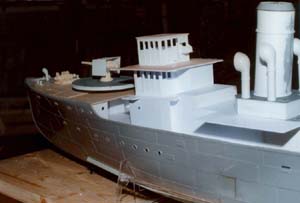
The lower bridge was now ready for completion. The front was a piece
cut to 40mm x 90mm. A deck for this was made with 10mmx20mm extensions
for the ladders at the forward edge, and 5mm at the rear to overlap the
galley. All of these were then taped in place to see what it looked like.
It was then that I realized that I have made a mistake in following the
angle of the waterline as the wheelhouse and compass house were to be
square in all dimensions, but that would not give a straight line appearance
to the front edge. To fix this I cut the front of the lower bridge down
to 37mm, and also did the same to the front edge of each lower bridge
side. The upper levels would now sit with all front angles vertical. ..
however as can be seen in the photos the entire bridge/galley structure
now appears to angle down towards the bow .. I decided to leave it for
now and turned to the wheelhouse and charthouse.
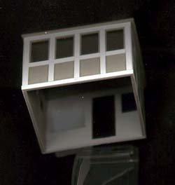
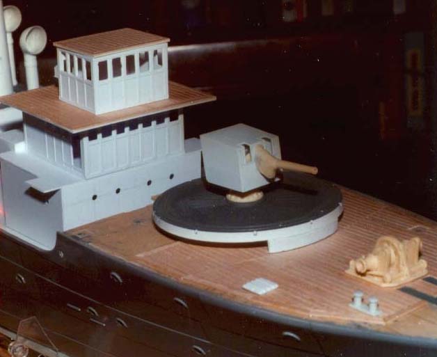
Modified kit wheelhouse as compass house |
The kit wheelhouse is more representational than accurate, but I decided
it could be modified into an acceptable compass house for the roof of
the wheelhouse. To do this I cut it at the level of the platform that
surrounds it, and also reduced the width/length to be four windows on
the front and three on the sides. A roof was added from the former rear
of the wheelhouse. The rear was cut from sheet styrene and glued in place.
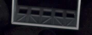
The wheelhouse and compass house on the real thing were constructed
of wood, not metal, and as such are heavily framed. At first I wasn't
going to bother with this, but the compass house looked rather stark as
is, so I glued .080 x .010 strips around the top, bottom and sides of
the house (next time I'll use a wider strip on the bottom), and also in
between each window. Another strip was added between each vertical frame
1mm below each window. I now noticed that I hadn't paid attention to the
fact that the kit windows are slightly different widths and that they
also differ in spacing between them on the front and sides – and
I hadn't matched these differences when I set up the house. Therefore
I used the Exacto blade to extend the outside windows on each side to
1mm from the frame.
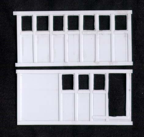
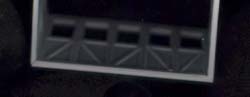
Wheelhouse prior to adding window framing |
The rear of the compass house requires a window, door and an alcove
for the charts to be added. First I added the four strips around the outside,
then verticals/horizontal for the window and door frames. The window and
door were cut out by making a few pilot holes with the Exacto blade as
a drill, these were then carefully cut out to be 1mm from the edge for
the window and flush with the frame for the door. The alcove was then
cut out and built from sheet styrene. Finally the door was built in a
similar fashion to the rest of the structure with frames around the outside
and below the window.
For the wheelhouse I cut four pieces of 32mm x 90mm out of .040 styrene.
Seven windows would be required on the front, and three on each side (plus
a door). After a few false starts I finally got these evenly spaced out
on the front by measuring 3mm in from each side and then going 5.5mm for
a window and 3mm for the gap. The .080 x .010 top and bottom and edge
strips were affixed, and as I was running out of this size stock I switched
to .060 x .010 for the verticals between the windows. I need not have
measured the windows, rather I just glued these at the centre mark for
each gap. Measuring down from the bottom of the top strip, I marked a
line 9mm down and added the horizontal strips at the bottom of the windows.
I then cut out each window as before using a new Exacto blade, this time
leaving a .5mm border. To this border I glued .020 square stock as a proper
frame
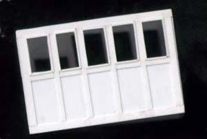
Scratchbuilt compass house with framing added around windows |
The sides were done in basically the same way, with the addition of
a door where the front window should go if the door was closed. I placed
the sides so that the front piece overlapped their leading edge, marked
off where the .080 cap strip would lie on the vertical to cover this join
and then where the verticals go for the door and window. The starboard
side was done first and I then traced out the location on this piece to
do the port side.
The port side differed in that I chose to make an alcove at the rear
of it for the ladder to the upper bridge section. This is shown on plans
as covered over with a wall or open, so I decided to use artistic license
and have it open.

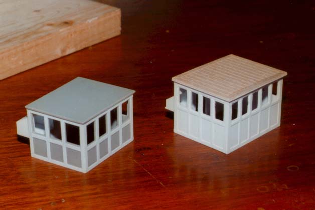
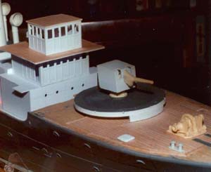
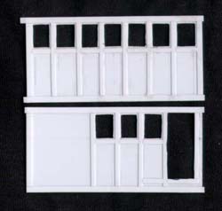
Kit conversion and scratchbuilt compass houses |
Eight hours after starting, the upper levels of the bridge were done.
.. except the converted kit compass house looked wrong now .. the windows
are too big (and too few), it is a little too narrow and it is also too
short ...... The next day I rebuilt it as per the wheelhouse, but with
five windows on the front, four on the sides and two on the rear (plus
a door and the chart alcove). The final step to these is to construct
the roof to the compass house and deck between it and the wheelhouse.
These were cut from styrene and basswood decking was epoxied to them for
a real wood deck. This really adds to the overall look.
This brings us back to the lower bridge. I finally decided to fix this
by going back and redoing the extension to the casing, but with the verticals
perpendicular to the bottom of it. Therefore only the rearmost cut is
now to be angled, all others are right angles and dimensions adjusted
accordingly.
 With
the exteriors done, I could now turn to the interior of the wheel and
charthouses. The same method of framing the outside was used on the interior
of each level and diagonal bracess added as well. In addition I also scratchbuilt
the interior furnishings for the two houses but that is for another time With
the exteriors done, I could now turn to the interior of the wheel and
charthouses. The same method of framing the outside was used on the interior
of each level and diagonal bracess added as well. In addition I also scratchbuilt
the interior furnishings for the two houses but that is for another time
|