Building the Matchbox/Revell 1/72 Flower Class Corvette: Part
4 - Getting Started & Basic Improvements
|
 |
Introduction
I have had many people contact me in regards to these articles and one
thing that has come up a few times is how daunting all of those parts
look in the box, and where to begin. This time we shall deal with getting
started, and some easy fixes to produce a better Flower. All that is required
is the desire to do it – and some sheet styrene.
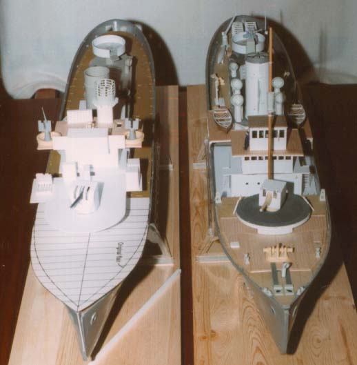
The Hull
 Whether
you intend to build a display model or one for radio-control, it is imperative
to properly prepare the hull. It is provided in four pieces, two bow halves
and two stern halves, with an ingenious join covered by the midships plating.
I spent a fair amount of time sanding and filing the slightly out of scale
keels on all four parts to make them as flat as possible so as to provide
the largest mating surfaces possible. Once that was done the two bow halves
were glued together using Faller Plastik Cement, and held together overnight
with various clamps. The next night I did the two stern halves, and the
final night was joining the bow and stern together. After all this was
done I coated the interior seam with epoxy. Whether
you intend to build a display model or one for radio-control, it is imperative
to properly prepare the hull. It is provided in four pieces, two bow halves
and two stern halves, with an ingenious join covered by the midships plating.
I spent a fair amount of time sanding and filing the slightly out of scale
keels on all four parts to make them as flat as possible so as to provide
the largest mating surfaces possible. Once that was done the two bow halves
were glued together using Faller Plastik Cement, and held together overnight
with various clamps. The next night I did the two stern halves, and the
final night was joining the bow and stern together. After all this was
done I coated the interior seam with epoxy.
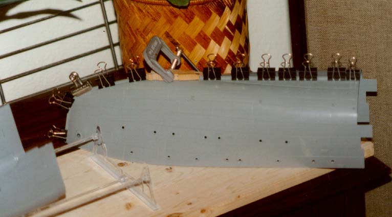
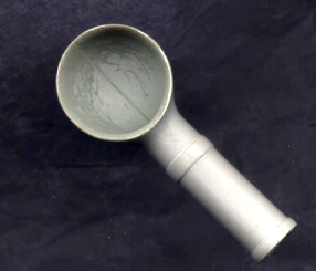
Vents
 The
first things I actually built were the vents alongside the funnel and
engine room casing. Once they have been glued together and the seams cleaned
up, the inside of the vent mouth was reduced using my #10 Exacto blade
and the cone shaped Dremel bit. This will result in a nice thin lip to
the vent, and makes a vast improvement over the original part. The interior
seam was later given a coat of filler and sanded smooth – after this
scan was done. The same thing can be done to all of the other vents. The
first things I actually built were the vents alongside the funnel and
engine room casing. Once they have been glued together and the seams cleaned
up, the inside of the vent mouth was reduced using my #10 Exacto blade
and the cone shaped Dremel bit. This will result in a nice thin lip to
the vent, and makes a vast improvement over the original part. The interior
seam was later given a coat of filler and sanded smooth – after this
scan was done. The same thing can be done to all of the other vents.
4" gun Platform
The first actual modification to the kit I did was to add the foot tread
pattern to the 4" gun platform on the bow. I had seen some great
photos of HMCS Snowberry with a radial tread pattern and decided I just
had to do it – this is what led to my current obsession with scratchbuilding/accurizing
the kit.
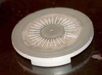 I
began by using a compass to draw two circles (50mm and 28mm) on the platform.
In order to center the compass I put the end of a bamboo skewer in the
opening and after cutting it flush, I carefully centered a locating hole
in it using the pointy end of the compass. Next was to draw a line through
the centre of the platform fore and aft, followed by another perpendicular
to the first, this was then halved, and repeated until I had 16 lines
drawn. These are where the foot treads will be placed. I
began by using a compass to draw two circles (50mm and 28mm) on the platform.
In order to center the compass I put the end of a bamboo skewer in the
opening and after cutting it flush, I carefully centered a locating hole
in it using the pointy end of the compass. Next was to draw a line through
the centre of the platform fore and aft, followed by another perpendicular
to the first, this was then halved, and repeated until I had 16 lines
drawn. These are where the foot treads will be placed.
For the first platform I built I cut one piece of .010 x.020 styrene
to length and kept copying it. For the second, I used a very handy gadget
called " The Chopper" this is a single edged razor blade affixed
to a lever. There is a metal edge attached at a right angle to the blade,
and there are adjustable plastic stops in 30, 45, 60 and 90° angles.
By locking these in place, multiple accurate pieces are possible in a
fraction of the time previously required. I have made extensive use of
mine.
With all the treads cut they were then glued in place using Testor's
Liquid Cement. I was using the old square bottle that I have had for at
least 10-15 years. . since then I have replaced it with a new round bottle
and find the new stuff (active ingredient MEK) is even stronger and fast
acting .. but is very potent if inhaled . . I spilt half the bottle and
still can smell it a week later. . USE VENTILATION.
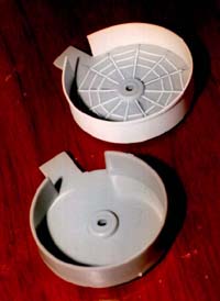 2pdr
Bandstand 2pdr
Bandstand
With the main gun platform looking good, I turned to the bandstand on
the engine room casing. The first thing to deal with is the totally out
of scale splinter shield around the entire structure. I cut this off using
the rotary saw with the Dremel. Once the edge was cleaned up I again drew
lines on the base for the foot tread pattern. This one has a 'spiderish'
style of pattern with straight lines connecting the radials.
With the tread added I then cut a piece of .020 styrene to construct
a new splinter shield around the structure. Once this was in place, a
.010 x.060 stripe was added along the top edge. If you want to go overboard,
emboss rivets on this piece before affixing.
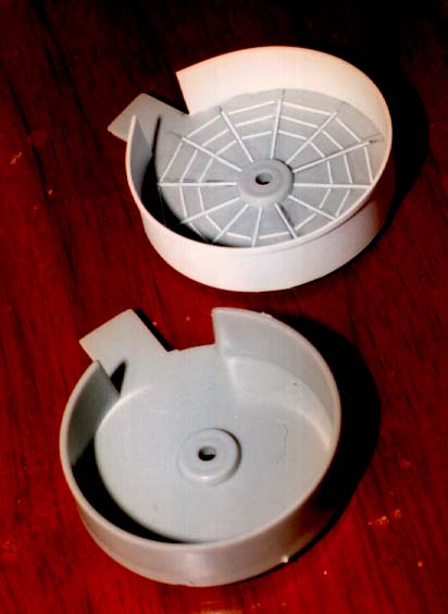
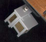
Engine Room Skylight
The kit engine room skylight is too short, too tall and has an incorrect
number of skylights. Using sheet styrene I cut two sides (2mm x 60mm)
and two ends (32mm x 7mm). The end pieces then had the angle cut in place
by centering a line at the middle of the top and connecting it to the
side at 2mm height. The four pieces were then glued together and the sloping
tops (17mm x 60mm) were added. The edges were sanded smooth and a .060
x .010 border added around the bottom edge.
 The
skylights were made of a piece of .010 glued on top of a piece of .020.
The bottom slightly less in height and width than the cover piece (cover
piece: 10.5mm x 9mm). Top and bottom were glued together and then affixed
to the skylight. To align them I drew a line approximately 2.5mm from
the raised centerline of the skylight. A perpendicular line was added
at the centre and the first lid was affixed there. I then eyeballed the
two outside pieces and then the one in between. The opposite side was
done the same way, with the addition of lining up with the first set of
lids. The
skylights were made of a piece of .010 glued on top of a piece of .020.
The bottom slightly less in height and width than the cover piece (cover
piece: 10.5mm x 9mm). Top and bottom were glued together and then affixed
to the skylight. To align them I drew a line approximately 2.5mm from
the raised centerline of the skylight. A perpendicular line was added
at the centre and the first lid was affixed there. I then eyeballed the
two outside pieces and then the one in between. The opposite side was
done the same way, with the addition of lining up with the first set of
lids.
The handles on each lid were made from .009 guitar strings .. I first
bent a 90° angle using some square tipped tweezers about 3mm wide. I then
used a pair of pointed ones that taper to about 1.5mm" wide. .. this
was what I used to set the centre width. I then cut them to length using
the cutter part on my needle nose pliers. To get them on the lid I drew
a line through all of them up about 2mm from the bottom. I then placed
the rung on top of the cover and marked where the hole should go. To drill
the hole I placed a short piece (3mm showing) of the guitar string into
my pin vise and used that as a drill. The rung was then placed into its
hole using tweezers. They could be left like that, but I gave each a dab
of CA on the rear to affix it. It took longer to type this out than it
did to do each one.
Hinges are .010 x .020 styrene. I am still debating on what to do for
the scuttles. GLS offers a detail set for them, but I don't really want
to go that way as I am enjoying scratchbuilding.
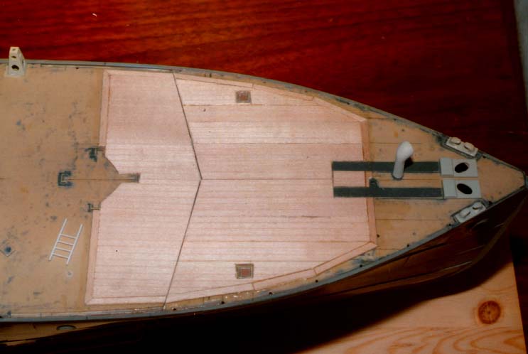
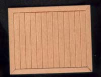
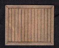
Wood decks
 The
kit provides you with a faux wood plank effect on the entire deck, however
the real ships only carried wood decking on the bow, bridge and around
the rear depth charge thrower. Therefore the raised planking had to go
– actually all raised deck locators also went. The same day I made
this decision I bought both a regular Dremel and a Mini-Mite, so I just
had to try them for this job.. . they did it, but also added many gouges
to the deck. So I decided to scrape/sand the rest of it away from the
rear deck. A much better idea, and it didn't take as long as I feared.
However I am now thinking it may have been easier to just cut a new deck
from sheet styrene. The
kit provides you with a faux wood plank effect on the entire deck, however
the real ships only carried wood decking on the bow, bridge and around
the rear depth charge thrower. Therefore the raised planking had to go
– actually all raised deck locators also went. The same day I made
this decision I bought both a regular Dremel and a Mini-Mite, so I just
had to try them for this job.. . they did it, but also added many gouges
to the deck. So I decided to scrape/sand the rest of it away from the
rear deck. A much better idea, and it didn't take as long as I feared.
However I am now thinking it may have been easier to just cut a new deck
from sheet styrene.
I searched for suitable wood to use for the deck and settled on laminate
strips used for edging tables and shelves. The plan being to cut it into
thin strips. . however as I left the hardware store I walked past a five
and dime store and they had a packet of coffee stir sticks for $1 . so
I bought them as well. Upon getting home I mentioned this to the Corvette
Mailing list, and one of them mentioned he had extra Model Expo planks
that he could send me if I so desired. .. Heck yes. ..
 Eventually
the planks arrived. They are 20" long x 3.5" wide and have a
plank width of 3mm. Since doing this I have found these planks in various
stores and see that they are available in other widths as well. One manufacturer
even precuts the planks and reglues them back together in a random pattern
so as to not have common grain. Eventually
the planks arrived. They are 20" long x 3.5" wide and have a
plank width of 3mm. Since doing this I have found these planks in various
stores and see that they are available in other widths as well. One manufacturer
even precuts the planks and reglues them back together in a random pattern
so as to not have common grain.
I prepared the bow for planking by drawing a line down the centre, another
at right angles to this at the centre of the gun platform mount and a
third one forward of the anchor winch. If you intend to have access to
the interior for an R/C model, the idea is to plank the bow in two pieces
on each of the two decks, with the join being on the centerline. If you
are doing a display only, the planking can be done in two pieces bridging
the join.
 The
planks themselves were affixed using 5 minute epoxy. The first one was
the strip along the rear edge and then the lengthwise strips were attached,
followed by the pieces along the edges. The real ship has a curved edge
following the shape of the bow, however I settled on a series of straight
lines. The
planks themselves were affixed using 5 minute epoxy. The first one was
the strip along the rear edge and then the lengthwise strips were attached,
followed by the pieces along the edges. The real ship has a curved edge
following the shape of the bow, however I settled on a series of straight
lines.
To finish the wood decking I'm using Weather-it by Rustall. It ages
the wood nicely as can be seen in these before and after scans of the
compass house roof.
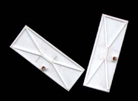
The Bridge
I was going to use the kit bridge as the basis for an accurized one
using new GLS stanchions in place of the thick railings supplied. When
I started to sand away the raised detail to apply the planking I decided
it was easier to just make an all new one out of styrene using the kit
parts as guides. The deck was planked once the structures were built.
Later I'll add GLS stanchions. I'm still not sure if I am going to add
canvas dodgers to them or leave the rails uncovered.
The wheelhouse is inaccurate in the number and location of windows.
This can be either used as is, or a structure similar to the wheelhouse
in last month's installment built. If the latter is chosen, than the height
needs to be adjusted to that of the kit part.
The Type 271 Radar platform can be replaced with a thinner styrene piece.
The raised pattern on it is actually supposed to be holes, so these should
be drilled into whatever platform is used. The diagonal supports under
the platform can also be made from thinner stock.
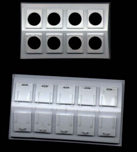
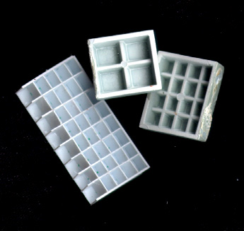
Storage lockers
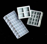  A
new signal locker was built from styrene with individual compartments
in it. The same can be done for most of the kit supplied lockers. I built
a new combination beef/vegetable locker from .060 angle and brass mesh.
For later Flowers these are in two separate components, so I still have
to do more of them for my other two Flowers. A
new signal locker was built from styrene with individual compartments
in it. The same can be done for most of the kit supplied lockers. I built
a new combination beef/vegetable locker from .060 angle and brass mesh.
For later Flowers these are in two separate components, so I still have
to do more of them for my other two Flowers.
Doors, Ladders and other Fittings
The kit doors are pretty basic, and can be dressed up by adding dogs
and handles to them.. Or new ones can be built in their place. For my
ships I built two styles of doors, watertight, and non-watertight. Here
is where "The Chopper" came in handy. . all of my doors have
the same dimensions.
 The
watertight doors began with a XxY coaming. Each corner was rounded slighlty
and then the door itself was made to be about 1mm within its boundary
on all four sides. To this was added hinges from .010 x .020 strip. For
the pivot of the hinge I placed a small section of heat-stretched sprue
at the rear of teh hinge. Dogs were made from other pieces of HSP glued
in place.. I thought about using 'L' shaped brass wire and affixing them
to overlap the door, but balked at that one. The handle was made in the
same way as for the engine room skylight. The
watertight doors began with a XxY coaming. Each corner was rounded slighlty
and then the door itself was made to be about 1mm within its boundary
on all four sides. To this was added hinges from .010 x .020 strip. For
the pivot of the hinge I placed a small section of heat-stretched sprue
at the rear of teh hinge. Dogs were made from other pieces of HSP glued
in place.. I thought about using 'L' shaped brass wire and affixing them
to overlap the door, but balked at that one. The handle was made in the
same way as for the engine room skylight.
 The
non-watertight doors started by drawing lines in the centre for where
the central brace will go. Then .010 x .020 strip was glued on the vertical
edges, leaving a .020 gap at teh top and bottom for teh cap strips later.
The central braces were glued to the centre of the door, followed by the
diagonal bracing. The top and bottom stripes were then added. The last
step was a small square .060 square of .010 glued for the handle locator,
and the handles are the round section rod that came with the kit for the
rails. Note that the doors are handed, with the handle being at the lower
of the two lines in the centre. The
non-watertight doors started by drawing lines in the centre for where
the central brace will go. Then .010 x .020 strip was glued on the vertical
edges, leaving a .020 gap at teh top and bottom for teh cap strips later.
The central braces were glued to the centre of the door, followed by the
diagonal bracing. The top and bottom stripes were then added. The last
step was a small square .060 square of .010 glued for the handle locator,
and the handles are the round section rod that came with the kit for the
rails. Note that the doors are handed, with the handle being at the lower
of the two lines in the centre.
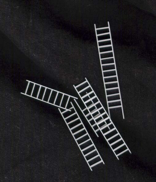
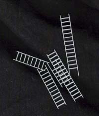 "The
Chopper" was also indispensable in making my ladders. I cut a full
package of .015 x .060 strip into rungs for the ladders. A jig was made
to align them properly from out of a 3/16" square piece of styrene.
I cut a series of slots into it equidistant apart and all at a shallow
angle. The rungs were placed into the jig and held in place by a piece
of .080 angle against one side. The exposed end of each rung was then
affixed to an .020 x .060 upright. After a few minutes the piece was slid
over slightly and the other side added. If a ladder needed to be longer
it was removed, and replaced with just one or two rungs in the jig allowing
more to be added between the uprights "The
Chopper" was also indispensable in making my ladders. I cut a full
package of .015 x .060 strip into rungs for the ladders. A jig was made
to align them properly from out of a 3/16" square piece of styrene.
I cut a series of slots into it equidistant apart and all at a shallow
angle. The rungs were placed into the jig and held in place by a piece
of .080 angle against one side. The exposed end of each rung was then
affixed to an .020 x .060 upright. After a few minutes the piece was slid
over slightly and the other side added. If a ladder needed to be longer
it was removed, and replaced with just one or two rungs in the jig allowing
more to be added between the uprights
The ammunition davits on the bow are shown as solid pyramids. I drilled
two holes into each side and cleaned them up so they don't appear quite
as thick.
Ship's Boats
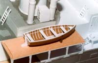 The
boats supplied with the kit can stand some extra detailing. For a complete
description of adding an interior see Part
Two: Building a 27' Whaler, the kit dinghies were done the same way.
Another option I have seen is to apply a canvas cover to the boats. The
boats supplied with the kit can stand some extra detailing. For a complete
description of adding an interior see Part
Two: Building a 27' Whaler, the kit dinghies were done the same way.
Another option I have seen is to apply a canvas cover to the boats.
Armament
The armament is a whole new area, and much work can be done improving
the kit items. So far I have done the following
– Scratchbuilt a new hedgehog
– Accurized the 2pdr
– Scratchbuilt a 4" Mk.IX BL gunshield and kitbashed the gun
inside
– Scratchbuilt a 4" Mk.XIX gun and kitbashed the gun
I still have to make new depth charge racks, so when that is done I
shall present all of them at once.
Conclusion
I think that about covers the basic conversions to the Matchbox/Revell
Flower. For those who have been following this, here is what my progression
has been to date
– Built first kit OOB – tore it apart and rebuilt as an
RCN Flower with. ..
– All new open bridge, gunshield, planked decks, bandstand, hedgehog
– Got second hull and did that to the same basic RCN standard
– Went back to first hull and after successfully making the minesweeping
gear I converted it to a short focsle
– Made deal for third hull...
– While waiting for third hull I made the Mk.XIX gun and platform
– Still waiting, so I did all the bridge structures, and started
planning the work to do on the hull.
So it now looks like the first hull has become the short focsle HMCS
Wetaskiwin. The second hull will be a late war Modified Flower, while
the third will be either a typical mid war RCN Flower (making use of the
items I originally built), or an RN Flower not using the RCN conversion
items I have already done ... should be a nice collection when I get them
done.
Addenda
 In
the past I have mentioned that I was planning on a series of ALPS decals
of various RCN Flower gunshield artwork. I finally sat down and tried
it .. first up is HMCS Snowberry for those of you building the kit. If
anyone would like a set, please contact me and I shall let you know the
particulars. Other RCN artwork is also available – those done so
far include: Arvida, Eyebright, Shediac, Shawinigan, Drumheller &
Wetaskiwin. In
the past I have mentioned that I was planning on a series of ALPS decals
of various RCN Flower gunshield artwork. I finally sat down and tried
it .. first up is HMCS Snowberry for those of you building the kit. If
anyone would like a set, please contact me and I shall let you know the
particulars. Other RCN artwork is also available – those done so
far include: Arvida, Eyebright, Shediac, Shawinigan, Drumheller &
Wetaskiwin.
I would like to ask that anyone with spare engine room vents (the four
around the skylight) please contact
me
|