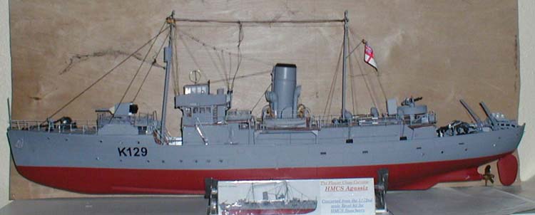
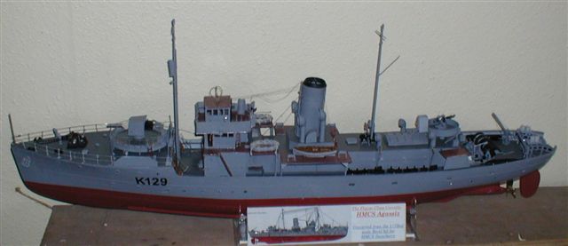
Converting the Revell Flower Class Corvette kit to an early
RCN Short Fo'c'sle Flower: HMCS Agassiz
|
 |
Introduction
This is a conversion that I have wanted to do for some time but have
not had the courage up until now to have a go. The major reference is
the book "Anatomy of the Ship
HMCS Agassiz" by John McKay & John Harland this gives all the details
required of the actual ship and her equipment. I also used the following
books "Canada's Flowers"
by Thomas G Lynch, and "Corvettes
of the Royal Canadian Navy" by Ken Macpherson for further information,
and of course the book Warship Perspective, "Flower"
Class Corvettes in World War 2 by John Lambert
 This
conversion entails shortening the forecastle of the kit, squaring off
the stern to the Canadian type, remodelling the bow by the removal of
the bow strake & prominent keel moulded by Revell. Repositioning the
ships boats and some of the armament. To put it simply a major rebuild
and severe kit bashing exercise This
conversion entails shortening the forecastle of the kit, squaring off
the stern to the Canadian type, remodelling the bow by the removal of
the bow strake & prominent keel moulded by Revell. Repositioning the
ships boats and some of the armament. To put it simply a major rebuild
and severe kit bashing exercise
For the actual conversion I used Bob
Pearson's templates. These templates give all details needed for
the conversion including new short fo'c'sle, new decks, superstructure
and bridge details. All that is required is the time and inclination
to get on with the conversion. Included in the package are pennant numbers
and gun shield art for other Canadian "Flower" class Corvettes.
The Conversion Starts
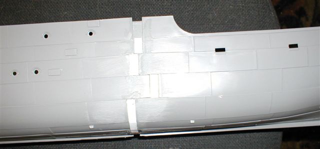
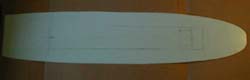
The stern is squared off by heating the material, I used a hair dryer
but any source of heat will do the job and reshaping the stern. This
will cause the hull to be about 1/2" short of the scale length. To bring
it back to the proper length, plates are cut from plastic card and the
gap between the two halves filled.
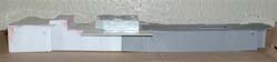
At the stern, new decks have to be made to fit the altered hull shape.
Cut out the apertures for the depth charge chutes and the minesweeping
fairleads. Deck surfaces have to be sanded down to remove the incorrect
Revel moulded planking and also various other deck markings have to
be removed which are now redundant. A new bridge and superstructure
built to the to the Canadian style, building the early commercial type
"A" bridge structure.
The hull is then turned upside down on the bench and the prominent
keel which Revell have moulded in which runs from the bow to the propeller
has to be removed, [look at the drawings on pages 36/37 & 41 of the
Anatomy of the ship HMCS Agassiz and it will be seen that no such keel
is shown]. This can be done in two ways either before the hull halves
are put together or afterwards, I prefer the latter as I think that
it makes for a more secure joint in the hull.
To do the actual removal I used my Dremel mini drill with the sanding
attachment and after a lot of work the result was that the prominent
keel had been removed, any small imperfections that are found can be
filled with body filler [I use P38 car filler] this is then sanded down
to obtain a smooth finish to the lower hull.
The hull joint can be reinforced on the inside of the hull to ensure
that the joint that you have sanded down from the outside is not weakened
in any way. For this I use Fibre Glass Resin but if you use this remember
that resin as it cures generates heat and must be cooled as it cures
to prevent any possibility of the hull distorting, I found the simplest
way of doing this is to place the hull in cold water while the resin
is curing. Once you are satisfied with the finish it is then time to
add the bilge keels to both sides of the hull at the positions indicated
in the kit. There will be small gap of about 1/2" in the middle that
requires building up here due to the hull sections being moved forward.
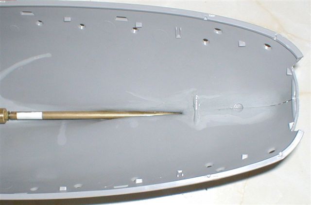
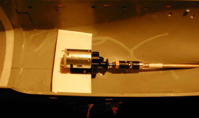
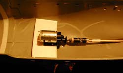 Once
the two halves of the hull are put together I then installed the motor
mount, which consists of a plastic card plate 4mm thick cut to size
and the centre line marked to allow for the gear drive. This is then
cut out and the motor fitted. The motor is then screwed down and the
alignment rechecked and the when satisfied the complete assembly is
stuck into place. Once
the two halves of the hull are put together I then installed the motor
mount, which consists of a plastic card plate 4mm thick cut to size
and the centre line marked to allow for the gear drive. This is then
cut out and the motor fitted. The motor is then screwed down and the
alignment rechecked and the when satisfied the complete assembly is
stuck into place.
For the rudder I used the kit rudder with a small commercial rudder
sandwiched between the plastic blades to give it the required strength
and at the same time provide the necessary rudder arm.
 Now
turn the hull back to the correct position and from the templates, cut
the lower guide for the removal of the excess hull to reshape the actual
hull for the short forecastle. For this I used mini drill and saw blade
attachment. When this is done the overlap of the fore and aft hull sections
must be carefully removed from inside the hull as this will show on
the bulwarks of the finished hull, again I used the mini drill but this
time with a sanding disc in place. A check was done on the drawings
in AOS against the hull of the kit and it was found that scuttles as
drilled in the kit were incorrect for the short fo'c'sle version so
new scuttles and eyebrows have to be drilled and marked in the proper
positions. Now
turn the hull back to the correct position and from the templates, cut
the lower guide for the removal of the excess hull to reshape the actual
hull for the short forecastle. For this I used mini drill and saw blade
attachment. When this is done the overlap of the fore and aft hull sections
must be carefully removed from inside the hull as this will show on
the bulwarks of the finished hull, again I used the mini drill but this
time with a sanding disc in place. A check was done on the drawings
in AOS against the hull of the kit and it was found that scuttles as
drilled in the kit were incorrect for the short fo'c'sle version so
new scuttles and eyebrows have to be drilled and marked in the proper
positions.
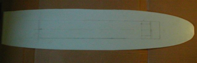
 When
this is complete it is time to turn to the decks. As was said earlier
Revel have planked all the decking and this has to be removed. I started
on the fore deck and after cutting the shortened fore deck to the length
required for the short forecastle, this was sanded down to remove all
the markings on the fore deck. A new main deck was cut from plastic
card using the kit deck and templates for the shape and length. This
avoids several joins in the decking if the kit deck is used and also
cuts out all the sanding required to remove Revell's marks. Scribing
the lines on the decking with a craft knife marks the deck plating on.
Inside the hull a line was drawn about 7/10ths down from the bulwarks
this is for a datum line for the main deck. A supporting strip was stuck
inside the hull along this line for the deck to sit on. When
this is complete it is time to turn to the decks. As was said earlier
Revel have planked all the decking and this has to be removed. I started
on the fore deck and after cutting the shortened fore deck to the length
required for the short forecastle, this was sanded down to remove all
the markings on the fore deck. A new main deck was cut from plastic
card using the kit deck and templates for the shape and length. This
avoids several joins in the decking if the kit deck is used and also
cuts out all the sanding required to remove Revell's marks. Scribing
the lines on the decking with a craft knife marks the deck plating on.
Inside the hull a line was drawn about 7/10ths down from the bulwarks
this is for a datum line for the main deck. A supporting strip was stuck
inside the hull along this line for the deck to sit on.
Measurements were taken from the AOS Agassiz for the new superstructure
and the distance from the stern marked on the new deck for the Canadian
type engine room casing and superstructure, double check the measurements
then when satisfied that they are correct cut out the opening in the
deck.
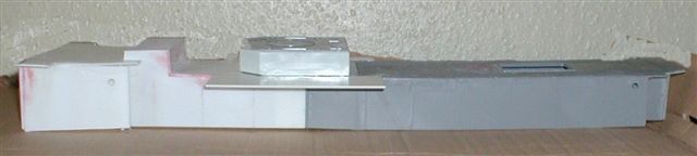
 When
you are satisfied that the new main deck is correct it is time to think
about the new engine room casing and its construction. The conversion
set contains a template shows the alterations that are required to carry
out this part of the conversion. When
you are satisfied that the new main deck is correct it is time to think
about the new engine room casing and its construction. The conversion
set contains a template shows the alterations that are required to carry
out this part of the conversion.
When the engine room casing is complete it is then time to look at
templates 8 & 9 both of which show the construction of the new forward
superstructure required for this type of ship. Note that these Templates
also cover the RN short forecastle version The kit funnel deck is used
with the front part G7 in the kit being replaced by a scratch made part
which goes right to the deck level
 A
new engine room skylight is required as the one provided by Revel is
too high and too short plus there are insufficient number of skylights,
five each side against four as moulded by Revell. The new skylight should
measure 60mm by 7mm and 10mm high. This is then placed in position 66mm
from the aft end of the engine room casing. Hinges and handles are added
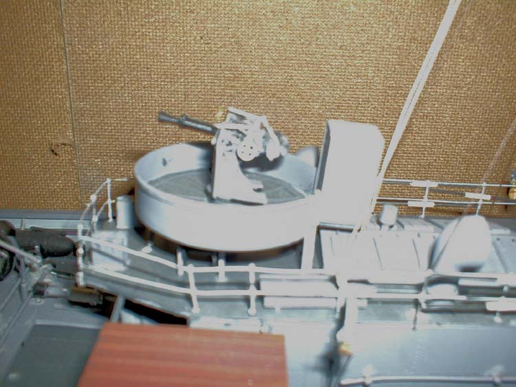
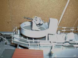
from strip plastic. The moulded on cone for the support of the 2pdr
has got to be removed from the kit position and the resulting hole filled
and repositioned where shown on template 7. A
new engine room skylight is required as the one provided by Revel is
too high and too short plus there are insufficient number of skylights,
five each side against four as moulded by Revell. The new skylight should
measure 60mm by 7mm and 10mm high. This is then placed in position 66mm
from the aft end of the engine room casing. Hinges and handles are added
from strip plastic. The moulded on cone for the support of the 2pdr
has got to be removed from the kit position and the resulting hole filled
and repositioned where shown on template 7.
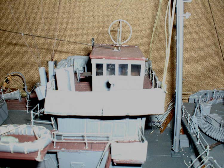
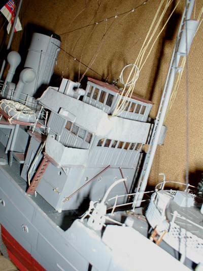
The construction of the new wheelhouse is now started using Template
11. Since both the wheelhouse and compass house are of timber construction
I used scribed plastic card sheet to simulate the planking, strip plastic
and angle to make up the framework round the timber of the structure.
 The
internal framework is put in place, as is a strip of plastic to support
the windows in position. The complete interior of the wheelhouse is
then painted teak colour to represent the wood construction of the structure.
Various internal details are such as wheel, telegraph and crew the radio
room details are added from scrap material to simulate radio etc. These
are shown on the template. The
internal framework is put in place, as is a strip of plastic to support
the windows in position. The complete interior of the wheelhouse is
then painted teak colour to represent the wood construction of the structure.
Various internal details are such as wheel, telegraph and crew the radio
room details are added from scrap material to simulate radio etc. These
are shown on the template.
Template 12 shows the dimensions required for the Compass House and
the decking over the wheelhouse and compass house roof. The planked
decks are again scribed plastic sheet. Also shown are the drawings for
the corrected RCN long fo'c'sle bridge, which also covers the later
type, fitted to the short fo'c'sle "Flower" class corvettes.
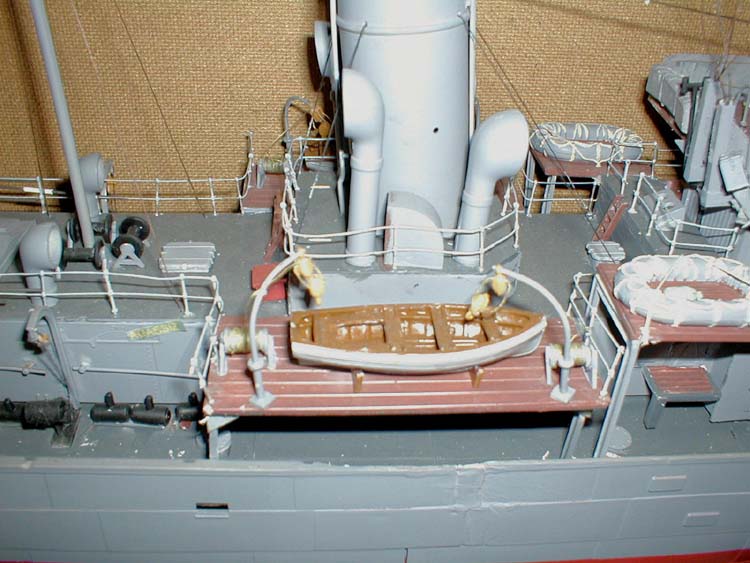
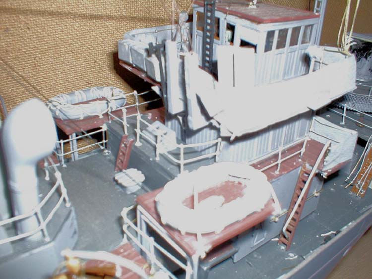
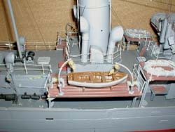 HMCS
Agassiz has the life rafts carried behind the bridge and at the same
level as the galley top and out the same width as the lifeboat deck
this shows the differences between ships. The templates show for other
early Flower class corvettes. The life raft platforms are made again
from plank scribed plastic and put into position. Before the complete
superstructure is fitted to the deck [for a sailing model] I put a raised
section of plastic of 1" all around the position that the superstructure
will sit on the deck, this does two jobs, HMCS
Agassiz has the life rafts carried behind the bridge and at the same
level as the galley top and out the same width as the lifeboat deck
this shows the differences between ships. The templates show for other
early Flower class corvettes. The life raft platforms are made again
from plank scribed plastic and put into position. Before the complete
superstructure is fitted to the deck [for a sailing model] I put a raised
section of plastic of 1" all around the position that the superstructure
will sit on the deck, this does two jobs,
[a] holds the super-structure in place and
[b] makes for a watertight joint between the deck and the superstructure.
 I
used a combination of fittings from the kit purchased fittings from
Sirmar and scratch builds others. Replacement fittings are available
from Sirmar & APS models. If you want to go all out, you can buy the
etched brass fittings from Great Little Ships . However I found that
they were rather expensive but the final choice is up to the builder. I
used a combination of fittings from the kit purchased fittings from
Sirmar and scratch builds others. Replacement fittings are available
from Sirmar & APS models. If you want to go all out, you can buy the
etched brass fittings from Great Little Ships . However I found that
they were rather expensive but the final choice is up to the builder.
For a sailing model I believe that the normal fittings are good enough
if cleaned up and more detail added. If, however, you want a display
model then etched brass is the way to go.
 The
various vents, hatches and skylights are now put in place on the superstructure.
The internal details in the compass house are taken from the AOS and
built and put in place. The glazing for the windows is now done and
the complete structure put in place. The
various vents, hatches and skylights are now put in place on the superstructure.
The internal details in the compass house are taken from the AOS and
built and put in place. The glazing for the windows is now done and
the complete structure put in place.
The supports for the life- boat decks and life raft decks are made
from [I beam, Evergreen 274] and are put in place. The supports for
the 2pdr platform made from [Evergreen angle 291] are cut and put in
place. The various lockers required are made from either adapting the
kit fittings or by scratch building and taking the dimensions from AOS.
The 4" gun shield is remade from thin plastic card [the original is
too thick] and the rivet lines on the plates scribed on. Internal braces
are put in place [using John Lambert's drawings for position] from Evergreen
angle 291.
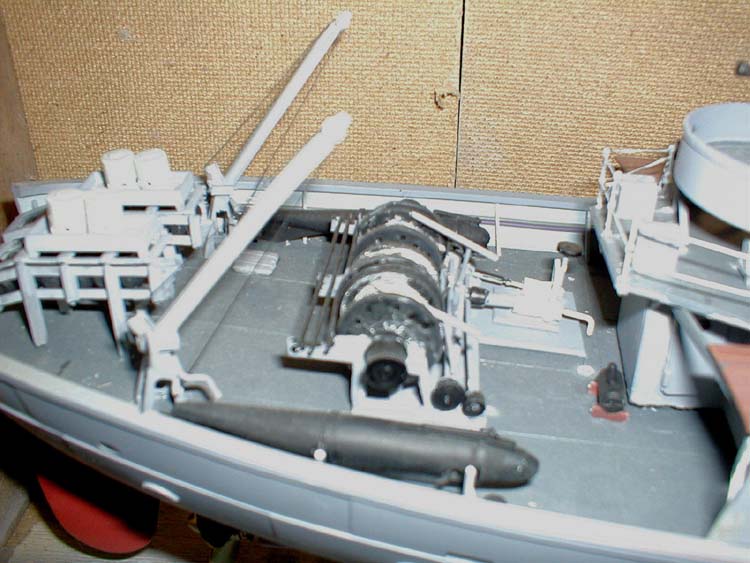
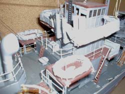
 The
next major part of the conversion is the construction of the actual
minesweeping winch, which
is a major fitting on the quarterdeck of these ships. The drawings in
the AOS are to 1/48th and have to be reduced to 1/72nd and all the measurements
are transferred to plastic card ready for cutting out and assembling.
If like me your maths are not very good [old age] that is my excuse
then the templates can be obtained from Bob Pearson. The
next major part of the conversion is the construction of the actual
minesweeping winch, which
is a major fitting on the quarterdeck of these ships. The drawings in
the AOS are to 1/48th and have to be reduced to 1/72nd and all the measurements
are transferred to plastic card ready for cutting out and assembling.
If like me your maths are not very good [old age] that is my excuse
then the templates can be obtained from Bob Pearson.
The foremast is situated in a false deck attached to the superstructure
to enable this to be detached without removing all the rigging from
the foremast to the deck. The false deck edge is feathered to conceal
the edge as much as possible and then it is painted as the proper deck
and marked for the plates, attached under the forward edge of the superstructure
the forward edge being in line with the break in the foícastle again
this helps to conceal the false deck edge as much as possible.
The foremast is then placed in position and glued down. The actual
rigging of the model will be left until the last thing as it will be
very simple to knock while fitting other details to the decking and
superstructure.
The dimensions for the paravanes are again reduced down from those
in AOS and constructed from plastic rod and tube then shaped and detailed.
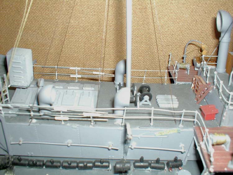
 Deck
stanchions [two packs are required from Sirmar] are added. Drill the
holes for the deck stanchions before adding the various items on the
superstructure; this makes things a lot less complicated. The deck rails
themselves being made from thin brass wire threaded through each of
the stanchions and the canvas dodger round the upper bridge is simulated
by using single sheet toilet paper and then sprayed grey to match the
hull colour and stuck into place. This when finished looks very much
like canvas and can be used for other details that require a canvas
look on the model such as lifeboat covers if you are fitting them. Deck
stanchions [two packs are required from Sirmar] are added. Drill the
holes for the deck stanchions before adding the various items on the
superstructure; this makes things a lot less complicated. The deck rails
themselves being made from thin brass wire threaded through each of
the stanchions and the canvas dodger round the upper bridge is simulated
by using single sheet toilet paper and then sprayed grey to match the
hull colour and stuck into place. This when finished looks very much
like canvas and can be used for other details that require a canvas
look on the model such as lifeboat covers if you are fitting them.
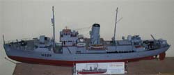
Minesweeping gallows are made and put in position, as are the otter
boards. Rigging is done and we have a new model based on the Revell
Flower class
|